 More Williams System 3 through 7 repair information is available! Go to my Resources page for the repair guide index. Lots more pinball at Mark's Pinball Page!
Firepower was the only Williams game produced that used the full memory addressing capabilities of the System 6 board. It used both a game rom at IC14 and 3 bipolar PROMS at IC21, IC22 and IC26. The 512K bi-polar PROMs have been unavailable for quite a number of years now as has the equipment to program them. This leaves the Firepower owner (or your trusty board repair tech) in a lurch when it comes to replacing the ROMs in the game. Fortunately, Williams posted a solution on their web site a few years back that allows all 4 game ROMs to be combined onto a single 2732 EPROM (commonly available) and used in a System 6 board with only minor modifications to the board. The downside to this modification is that the board can ONLY be used in a Firepower unless the modifications are reversed. Unless you are an operator of a lot of Williams System 6 machines (there might still be one out there somewhere!), this shouldn't present a problem to you. Disclaimer: Perform this modification at your own risk. I cannot be held liable for any damage you may inflict on your boards or yourself. Getting Started - Parts needed: You will need to obtain the following parts: 1. A working System 6 or 6A MPU board. If your board is not working prior to doing the modification, you'll have no clue as to whether your modifications are causing new problems or you board had problems other than bad ROMs. If you think your board is not working due to ROM problems with the existing Firepower ROMs, I would suggest downloading another System 6 game rom (you can find them here), and trying it in your board prior to make the modification. Make sure you change the jumper from J4 to J3! 2. One 4.7K 1/4 or 1/2 watt resistor 3. Two 1N4148 signal diodes 4. Some thin gauge wire and heat shrink tubing 5. A Firepower "Combo" ROM. If you have access to a ROM burner, you can obtain the code here and burn the image onto a 2732 EPROM. If you don't have access to a ROM burner, you can purchase one here. Tools needed: - A very sharp Xacto knife Making the modifications: 1. Remove the ROMs at IC14, IC21, 22 and 26. 2. Remove the jumper at J3/J4
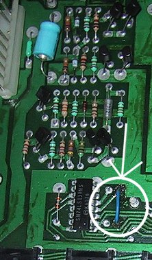
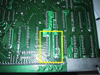
3. Flip the board over and locate the solder pads for IC14 on the back of the board:
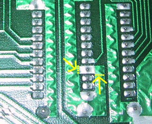
4. You are going to need to cut the traces on both sides of pin 21. This will remove the +5 volt connection from this pin. The photo below shows you where to make the cuts. I use a very sharp X-acto knife to make the cuts. IMPORTANT! When you think you've made the cuts, use you DMM to check to make sure you really have isolated pin 21.
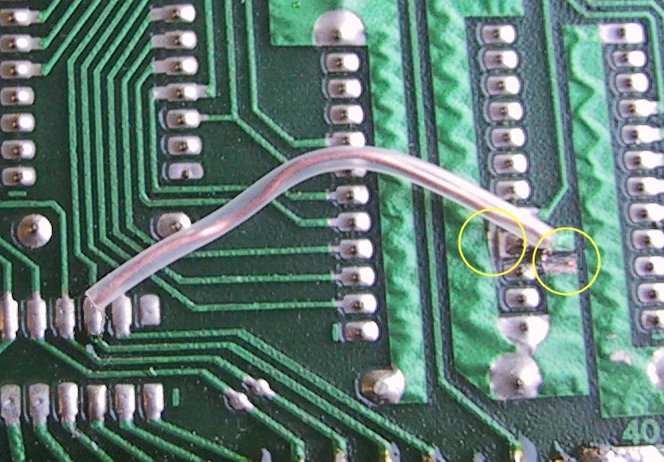
5. After you make the cuts, using your small drill bit, drill a hole just to the right of the pin 21 of IC14. Locate pin 14 of IC30 (this is a unused chip next to IC14, just the pads are on the board). See the photo below and run a jumper from pin 14 of IC30 to the small hole you drilled next to pin 21 of IC14. You can get away without drilling the hole, but run the risk of the jumper breaking off.
This step removes the +5 volt connection from pin 21 and connects it to address line A11.
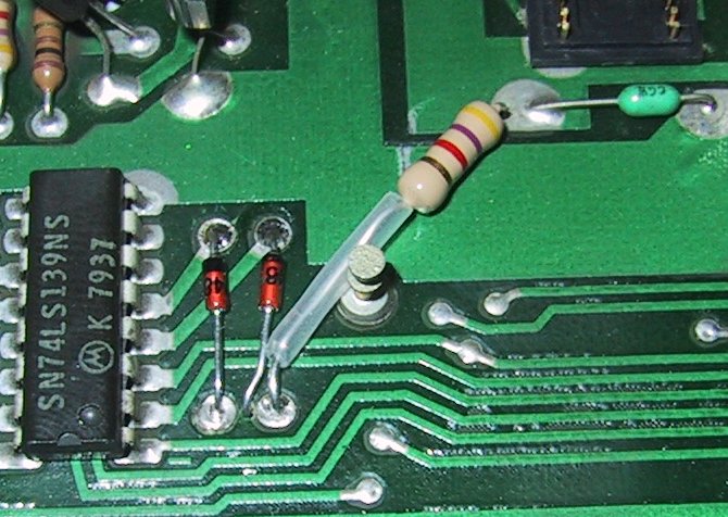
Then drill another small hole to the left of capacitor C17. Install the 4.7K resistor between C17 and the J3/J4 jumper lower pads. Make sure you don't short the resistor to the test point by using a short piece of heat shrink tubing on the resistor lead.
7. Install the 2732 "Combo" ROM into IC14. Use the existing Green Flipper ROMs 1 and 2 in IC20 and IC17. Summary: That's it! Your game will operate the same way it did before, there are no upgrades or modifications to the game's software. There is also another published method of doing the conversion that does not use the two signal diodes and pull-up resistor. I have tried this method (its the same as this, just minus the extra parts) and found that it works on some boards, but not all. Adding the two diodes and resistor then brought these boards to life. I would suggest always adding the diodes and resistor, why risk your board not booting. Enjoy your game! |