|
3.
What makes up the "Power Supply" There
are actually 6 different "power supplies" that exist in the
game: 1. +5vdc regulated logic power
2. +12vdc unregulated (for the reset circuit)
3. +18vdc Lamp power (for game controlled lamps)
4. +28vdc Solenoid and Flipper power
5. +100vdc and -100vdc display power
6. +6.3vac General Illumination lamp power Also,
please note that the Sound Board has its own power supply, so if your
sound is out, don't start tinkering with the main power supply. The
photo below shows a typical power supply setup out of a System 6
game. All of the components are shown. You have the power
supply board, the transformer, the two bridge rectifiers, the fuse block
and the lamp filter capacitor. 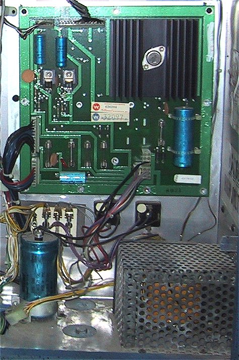
3.1
Check the Fuses! Please, before
doing any further troubleshooting, check your fuses! System 6 games
have 9 fuses, with earlier games having a few less. Here
is the fuse layout for a System 6 game: On
the Power Supply board:
F1 - Display Fuse, 1/4 amp slo-blo
F2 - Solenoid Fuse, 2 1/2 amp slo-blo. Probably the most
common fuse to blow, you should keep a good stock of these.
F3 - Lamp Fuse, 8amp (not slo-blo!)
F4 - Flipper Fuse, either a 10amp or 15amp slo-blo. If your
game has 2 flippers, then use a 10amp, 3 or more then use a 15amp.
F5 - Logic Supply Fuse, 4amp (also not slo-blo!)
On the Fuse Card (left to right):
6F1 - General Illumination Fuse,
20amp
6F2 and 6F3 - Logic Supply main fuses, 4amp slo-blo
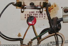
In the cabinet:
AC Line fuse - 7.5 or 8 amp
3.1.1 Fuses and General
Illumination on System 3 and 4 games Williams
did a neat thing, they left the design of the power supply the same from
1977 through late 1980, but wired things differently through the power
supply. System 3 and 4 games (all
games through Flash) do not have the fuse for the Flipper power on the
power supply (F4). The fuse is located under the playfield near the
flippers. Fuse holder F4 is
present on the power supply on these games, but the circuit isn't used on
games from World Cup through Flash. The
first two solid state games from Williams, Hot Tip and Lucky Seven, use F4
as the GI fuse! (conFUSED yet?). These games routed the GI
power through Power Supply board and the .156" connectors. The
photo below shows the GI connector from a Hot Tip and the associated burn
marks on the connector. Williams smartly removed the GI from the
Power Supply board by World Cup, but had a lapse of judgment and put it
back onto the Power Supply board in System 7 games, albeit with a larger
Molex connector, but the same burnt connector results. 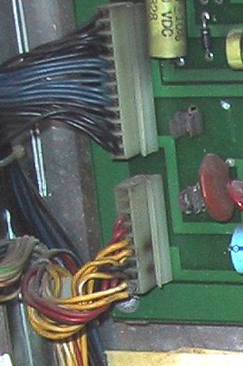
System
3 games remind me of looking under the hood of a '67 Mustang, not much
there but what makes it go. Here is an early System 3 power supply
setup with no fuse card. Later System 3 games and all System 4 games
had a single fuse card to hold the GI fuse. The logic power supply
was not fused before the diodes and filter capacitor as in System 6 and
later games. 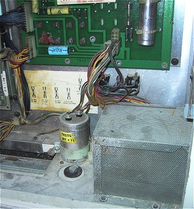
3.2
Lets start at the beginning ....
with the line cord. It needs to have its ground intact! That
means all 3 prongs still on the plug. Most games that I've come
across have the ground prong cut off to accommodate cheap extension cords
or antique electrical wiring. The game uses ground as the return
path for just about everything, so if you feel a little buzz when you
touch the side rails of your game, that means you're the quickest path to
ground! If your line cord has been
doctored, or is showing its age in any way (i.e., electrical tape wound
around it anywhere), replace it immediately. Go to Home Depot or Lowes and buy a
decent 10amp 15' extension cord and cut off one end and use it to replace
your existing cord. Just make sure you wire the ground in properly.
Its a good idea to replace the line cord on all older games anyway.
The cord was subject to an excessive amount of stress where it comes
through the backbox. Williams did not use any type of strain relief device
here, and the cords will fail eventually. 3.2.1
The AC Circuit In the cabinet is
the AC circuit that consists of the AC fuse, a utility outlet, a Varistor,
the off-on switch and a Line Filter. All of these components except
the on-off switch are mounted on a white board on the left side of the
cabinet. 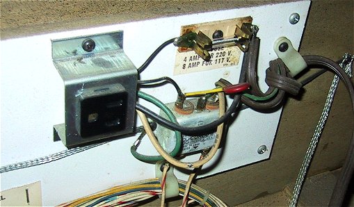
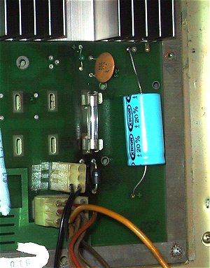
The
Varistor is a voltage spike protection device. Its what looks like a
large red ceramic disk capacitor wired across the terminals of the Line
Filter. Think of it as a one-time surge suppressor. I found
this definition of a varistor through a Google search: The
varistor is a surge protection device that is connected directly across
the AC input. When a power surge or voltage spike is sensed, the
varistor's resistance rapidly decreases, creating an instant shunt path
for the over-voltage, thereby saving the sensitive control panel
components (hopefully). Because the shunt path creates a short circuit,
the varistor and the line fuse are be damaged or weakened in
the process If you just see two
metal leads sticking up off of the line filter or something that looks
like a burned disk capacitor, then you know your game
was subject to a power surge sometime in its life. The game will run
fine without the varistor, but is no longer protected form surges and
spikes (i.e., a surge caused by a nearby lighting hit).
|
Example
of a blown varistor
(photo by Jean - jmdb@rogers.com) |
Should
you use a surge protector strip like you would with a computer? If
the varistor is intact, then there is no reason to use a surge
protector. Most surge protectors (IMHO) that you buy at the home
store aren't much protection to begin with, so make sure you replace the
varistor if its blown. The Line
Filter (the silver box), is used to suppress radio frequencies from making
into your game. Your line voltage is at 60hz, however your house
wiring acts like a big antenna picking up just about every television
signal, cell phone signal, radar, what have you, that is in your
area. If these frequencies made it through to the MPU board they
could disrupt the operation of the CPU chip. The same thing applies
in reverse, the filter prevents the high frequencies from your game's CPU
from flowing back into the AC circuit. The
off-on switch is a standard SPST toggle switch. They can wear out
after time, so if there is any "give" in the switch when you
turn your machine on, then it might be a good idea to replace the
switch. They're readily available at Radio Shack. 3.2.2
The Transformer The 120vac line
current is brought up to the Transformer's primary windings via 2
white/red wires. While it is rare for your transformer to fail, its
not unheard of. They tend to go "all at once" in a nice
puff of smoke and a wonderful smell, but I have talked with people who
have had failures of some of the secondary windings. Its not the
first place to check, but it shouldn't be overlooked. 3.2.2.2
Conversion from 220 Volt Wiring (System 6 and 7 games) Starting
with System 6 games, Williams wired the transformers so that the only
backbox change required was a jumper change to switch the game from 120 to
220vac operation. Since Williams hard wired in the line cords, a new
line cord would also have to be soldered in. The utility outlet in
the cabinet was also specific for the country of operation. Games
of this era are still being imported back to the United States, so you
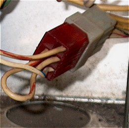
could find yourself faced with a 220 volt wired Black Knight. To
determine if your game is wired for 120 or 220 (independent of what type
of line cord plug is on the game), look at the plug that connects the line
voltage to the transformer. 220 volt games used a red connector from
the factory (see the photo below) and 120 volt games used a blue
connector. 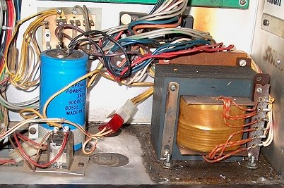
(Early Black Knight wired for 220 volt operation - photo by Todd G.)
Look
at the line voltage connector. If it has one jumper, from pins 2 to
5, then your game is wired for 220 volt operation. If it has two
jumpers, from pins 2 to 6 and 4 to 5, then its wired for 120 volts (photo
below). 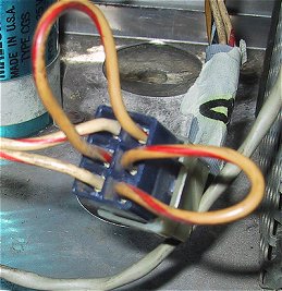
(System 6 line connector jumpered for 120 volt operation
(left) and connector jumpered for 220 volt operation (right))
To
switch your machine over to 120 volt operation follow these steps: 1.
Cut off whatever line cord is currently on the game. Replace it with
a good quality 14 gauge 3-prong (grounded) line cord. You can use an
extension cord and cut off the female receptacle if you can't find a long
enough replacement cord. 2.
Your game probably has a very foreign looking utility outlet in it.
Rather than attempt to replace this, it should be cut out of the circuit. 3.
Wire your new line cord as follows:
- Solder the hot lead (if you know which
one it is, usually the copper colored wire if there are two colors), to
one side of the fuse holder.
- Solder the other side to one lug of the line filter (the line filter
is rated 120/220 so it does not need to be changed).
- Solder the ground wire (usually the green wire) to the ground lug on
the line filter.
4. Solder a short wire (at least 16
gauge) between the fuse holder (the lug without the line cord) and the
other lug of the line filter. 5.
Replace the line fuse with either an 8 (2 flipper games) or 10 amp fuse (3
or more flipper games). The fuse in the game will only be a 4 amp
fuse. 6. Locate the
transformer. In System 6 games it is always in the head. In
early Black Knight games it will also be in the head. Later Black
Knight games and later system 7 games have the transformer in the cabinet. 7.
Remove the jumper between pins 2 and 5. If you have the proper
tools, you can add the new jumpers between pins 2-6 and 4-5. If not,
you can cut off the wires from the transformer side of the plug and solder
and tape each pair together. This will make your game a "120
volt" only game, but I doubt you'll be selling it overseas any time
shortly. 3.2.3
Blowing the Line Fuse Your game's
circuits are protected by a multitude of fuses and its rare that the main
line fuse in the cabinet will blow. If it does however, then follow
these steps to find the short: 1.
Disconnect the transformer from the AC circuit. The connector is in
the backbox near the transformer. On System 3 and 4 games this is a two
plug Molex Connector with White/Red wires, on System 6 games it is
typically a 4 plug Molex Connector with the 2 white/red wires and a small
"loop" of white/red wire on the other two connectors. If
the fuse still blows with the transformer out of the circuit, then your
problem is in the cabinet wiring. If the fuse holds, reconnect the
transformer and move to the next step. 2.
Isolate transformer from the game by disconnecting all of the
transformer's secondary outputs. There can be up to 6 connectors
that need to be disconnected. There are two large Molex connectors
in the lower center of Power Supply board, one connector that leads to the
Sound Board and 3 GI connectors. If
the fuse holds, then start reconnecting these connectors one at a time
until you locate your short. If the
fuse blows, then move on to the next step. 3.
The two bridge rectifiers mounted in the backbox are "hard
wired" to the transformer. Sometimes the lug connectors can
just be pulled off, but you may find that yours have been soldered.
You need to remove one red lead from the left bridge and one blue lead
from the right bridge. If your fuse blows with these connected, then
you have isolated your problem to the transformer. First check all of the
wiring carefully to make sure there are no shorts on the connectors, and
if after this check the fuse still blows, you'll need to replace your
transformer. If the fuse holds, then
one of your bridge rectifiers is blown. Reconnect the bridge
rectifiers one at a time to see which one is bad and then replace
that bridge. 3.3
The good stuff, the Power Supply Components As
I said in the introduction, a lot of people "repair" the wrong
part of the power supply based on a good deal of incorrect information and
bad advice floating around the Internet. Before
we go over the different supplies, here is a photo of a Power Supply board
with the major components labeled: 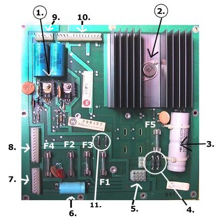
1. The 100 volt display power
supply. The majority of the components on the board are part of the
display power circuit. 2.
The +5volt DC regulator for the logic power supply. 3.
The 12,000uf filter capacitor for the logic power supply. 4.
The rectifier diodes for the logic power supply. 5.
The power inputs. The larger Molex connector on the bottom is the
power inputs and the smaller connector is the lamp and solenoid ground
input. 6. The
filter capacitor for the +28vdc solenoid and flipper power supplies. 7.
Solenoid and Flipper power output. 8.
Lamp and Solenoid power output. 9.
Display Power Output. 10.
Logic Power Output.
3.3.1 Logic Power Supply (+5vdc and +12vdc) The
logic power supply is what powers the MPU board and the logic functions on
the driver board. There are two voltages supplied from the Logic Power
Supply, +5 volts dc regulated and +12 volts dc unregulated. Below is
the schematic of the power supply. Note that the +12vdc is taken just
before the regulator. 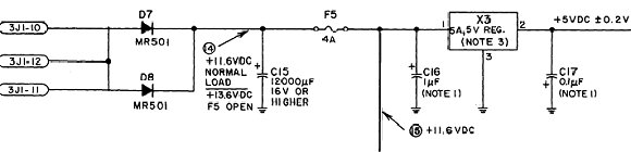
(Williams
System 6 schematic) The
two components that are most likely to fail in this circuit are the large
filter capacitor, C15 and the voltage regulator X3 (mounted in the large
heat sink). Both of these failures are due to heat and age. If
an electronic engineer looked at the circuit, they would give you a
different response (the diodes). The
large 12,000uf filter capacitor has most likely dried out. If the ends
of the capacitor have started to bulge out, then you capacitor has dried out
and its time to replace it. You can test the capacitor by using your
meter set to AC and put the red lead on the positive side of the capacitor
and the black on the negative lead. If you see more than .3 volts,
then you need to replace the capacitor. If
you're ordering parts for your game, its a good idea to replace the diodes,
filter capacitor and voltage regulator. Your logic supply will be
ready for the next 20 years. Finding
Replacement parts: Diodes
D7 and D8 are listed as MR500 or MR501 diodes on most schematics.
This cross-references to a 1N5401 which is available from Mouser for 16
cents. The 5 volt
regulator is a positive 3amp regulator in a TO-3 case. The current
regulator available is a LM323K, available from Mouser for $3.48. Much
more difficult, if not impossible to find, is C15, the large 12,000uf
axial lead filter capacitor. They just don't make these things anymore! I
have looked and looked and not found a replacement. Most capacitors
today are of the "snap-in" type with interlocking lugs that
"snap" into a circuit board. Williams power supplies call
for capacitors with axial leads, and they are not made in these sizes
anymore. What
to do? If you want to stick with axial lead capacitors, 10,000uf
16 volt electrolytic capacitors are commonly available, as are smaller
sizes. Capacitors in parallel work like resistors in series, the
total value is the sum of all the capacitors in the circuit. I use a
10,000uf 16 volt and add a 2,200uf 16 volt in parallel to bring the total
value up to 12,200uf.
 |
Capacitors
made today are about 1/4 the size of their counterparts from the
late 70s and early 80s. So don't be shocked when your order
comes in and you see this miniature capacitor! |
You can order both the
10,000uf and 2,200uf capacitors from Mouser. The 10,000uf is $3.75
and the 2,200uf is $1.00. You can use capacitors that are rated
higher than 16volts, but don't use any that are lower.
You can also use other types of
capacitors, such as radial lead or "snap-mount" in place
of the axial lead. They all work the same, its just the
mounting that's different. Snap-mounts are the most common
today, and are available in 12,000uf and 18,000uf sizes at the
proper voltage rating (16 volts or higher). You would need to
attached the capacitor using wire-ties through the the board, then
just solder leads to the capacitor and then solder the leads into
the existing holes. Might not be the cleanest looking, but it
gets the job done. |
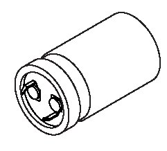
(Snap Mount Capacitor drawing from
Mouser Catalog) |
3.3.2
That pesky +12volts If
you look at the schematic above, you'll see a label for "+11.6 vdc"
which is what is commonly known as the +12v unregulated supply. This
voltage is used by the reset circuit on the MPU board to determine if the
power has been turned off. Since the +5vdc regulator will keep the
+5vdc going for a few milliseconds while the capacitor is discharging, the
MPU needs to know when you've shut down the power so it can shut down any
circuits that may get damaged while the board is losing power. This
voltage does not have to be 11.6 volts or 12 volts! Depending on your
line current, this will fluctuate between 10.5 and 13.5 volts. So
don't look for problems where none exist, it is a common beginner mistake (I
can raise my hand to this one also) to think that if this is off a few volts
there is a problem. 3.3.3
Display Supply - +100v and -100v The
Display power supply, otherwise known as the high voltage supply, provides
the 100 volts needed for the displays, both positive and negative with
respect to ground. This
circuit consists of two rectifier diodes, two filter capacitors and a set
of transistors and zener diodes that act as a voltage regulator. The
input voltage to the circuit coming from the rectifiers is 120vdc, however
the Zener diodes are used to regulate this voltage to 100vdc. 3.3.3.1
What's the deal with these extra Capacitors? (the 300 volt supply) The
original design for the power supply board called for a +300vdc power
supply to provide an extra "kick" to get the display gas to
ionize. System 3 games utilized this extra power supply, but it was deemed
unnecessary during the System 4 game production and was dropped. If
your power supply has some "extra" capacitors and diodes that
aren't on the schematic, then you have an older power supply. The
300 volts was produced by what is known as "voltage triplet", utilizing
two diodes and two capacitors to triple the incoming AC voltage. If
you have a System 3 game and your 300 volt supply isn't working, there is
no need to attempt to repair it. You can safely remove the extra
parts and not effect your displays. 3.3.3.2
Lowering the Display Voltage The
100 volts is the "cathode" voltage used to ionize the gas in the
display tubes make it glow. The displays will operate at lower
voltages, and it has been proven that this will greatly extend the life of
the displays. Since the displays in your game are probably already 10
years past their life expectancy, this might not be a bad idea. While
the displays will be a bit dimmer, they were originally designed to be
seen in brightly light arcades and also at outside venues with a good deal
of sunlight. In your dim basement game room, running your displays
at a lower voltage actually looks better, with a "crisper"
looking digit. This is
probably the most cost effective modification that you could ever make to
a pinball game. With new 6 digit displays tubes averaging $24 each,
a 50 cent investment in lower voltage Zener diodes can save you a
bundle. You
want to replace the two 100 volt Zener diodes, Z2 and Z4, with 91 volt, 1
watt Zener diodes, type 1N4763A. These are available at almost every
electronic supply house. 3.3.3.3
Repairing the high voltage supply, the Unavailable Parts Scenario If
your displays are dead, before hacking away at the High Voltage supply or
even bring out the multi-meter, the easiest way to determine if they're
getting voltage is to look for a small orange glow in the corner of the
display. If
you see this, then you're getting the proper voltages to the displays,
just not the correct data to drive them. And of course, check the fuse
first. Its amazing
that you can still obtain 99% of the parts used in these 20+ year old
games. However, there is one part used in the high voltage supply
that is no longer available and a second that is hard to come by. These are
the two 100 volt transistors used in the high voltage supply, the SDS201 and
the SDS202 transistors. The SDS201 has an NTE equivalent, NTE171
which can still be found if you look hard enough. The SDS202 NTE equivalent
is NTE296, which is a bit trickier to locate. All
is not lost however, there are equivalent parts currently available that
you can substitute. There is a small caveat however, the
configuration of the replacements is different from the originals, so you
won't be able to just drop in the replacement transistor. For
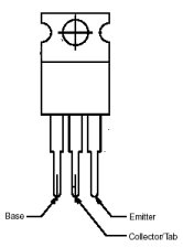
Q1 (the SDS201), you can substitute a MJE15030 or a NTE54. For Q3
(the SDS202) you can substitute a MJE15031 or a NTE55. The MJE parts
are much cheaper than the NTE equivalents, so look for those first. The
caveat is that the MJE and NTE substitutes have different a different leg
configuration. The original SDS transistors at Q1 and Q3 have a leg
configuration of E-B-C (emitter, base, collector), while the MJE/NTE parts
have a leg configuration of B-C-E (base, collector, emitter).
NTE 54/55 configuration
(courtesy NTE) |
SDS 201/202
configuration
(Williams schematic) |
 |
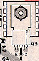 |
There are two ways you can
install the MJE/NTE transistors. The first requires you to bend the
leads of the new transistors to make them fit and the second is to drill a
new hole in the board and jumper the connections on the bottom of the
board. I have tried
both, and would recommend the first method. If you look at the photo
below, what you need to do is to GENTLY bend the emitter tab and have it
"tuck" under the collector and base tabs. I would
recommend that you put a short length of insulation over the emitter tab
to make sure you don't short out the transistor.
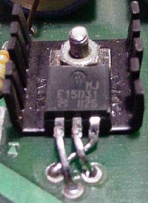
(photo by ?)
The
second method requires drilling and doesn't result in a clean looking
result. You won't be able to bolt the heat sink back down onto the
board. If you are interested in how to do it, it is well documented
at:
http://www.aros.net/~rayj/action/tech/wmshv.htm The
other two transistors in the high voltage circuit, Q2 and Q4 are also
obsolete part numbers, but cross reference to commonly available parts
(that have the same leg configuration!). Q2
(MPS D52) - You can use a 2N5401 or a NTE288
Q4 (MPS D02) - You can use a 2N5550 or a NTE287 3.4
The Lamp Circuit Williams
solid state pinball machines use +18vdc to drive the MPU (game) controlled
lamps. If you're asking yourself "how do they use the same bulb with 18
volts dc and 6.3 volts ac and they are exactly the same brightness?"
you would be asking a valid question. While the lamp supply does
indeed output a constant 18 volts dc, the driver board "pulses"
the 18 volts to the lamps, turning them on and off very quickly so that they
never get to the full brightness that a steady 18 volts would achieve, but
to the brightness that the 6.3vac of the GI circuit achieves. Are
you still asking "why?". The driver board cannot switch ac
voltages, so dc voltages have to be used. One of the many reasons that
you have AC coming into your house instead of DC is that it was found out
early on in the days of electric power that light bulbs last longer when
powered by AC rather than DC. The "pulsed" DC that Williams
uses mimics some of the characteristics of AC and results in longer bulb
life than if a constant DC was applied to the bulbs. Bally
evidently did it differently, using constant switched DC. If you're
really curious about the subject, click
here to link to groups.google.com for an avid discussion regarding the
subject from back in 1997. Now,
back to our regularly scheduled program (the circuit itself...) The
lamp supply has only two components, a large bridge rectifier and an equally
large filter capacitor. The photo below shows the large 30,000uf
filter capacitor and the two bridge rectifiers mounted on the backbox.
The one on the right is used for the lamp supply. This is a 35amp, 400
volt bridge rectifier that is available at most large electronic houses. 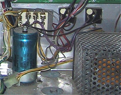
Most
MPU controlled lamp problems are driver board associated. However if
all of your MPU controlled lamps are off and everything else is working,
check the voltage coming out of the power supply. Using a DMM, measure
the voltage from pin 5 of connector 3J4 on the power supply (number 8 in our
photo in section 3.3, count up from the bottom for the pin) to ground.
If you're not getting 18 volts, then pull the large 12 pin molex connector
and measure the voltage between pin 1 of the connector and ground. If
you're still not getting anything, then its time to replace the bridge
rectifier. Should you
replace the big can capacitor? They are hard to find and expensive, so
unless its leaking and/or bulging or you've replaced the other components
and you're lights still aren't working, don't panic over keeping the
existing one. 3.5
The Solenoid Power Circuit The
solenoid circuit consists of a bridge rectifier mounted on the backbox (In the photo above, its the one
on the left. Like the lamp rectifier, its a 35amp, 400 volt
rectifier. On the
Power Supply board there is a 47volt varistor used to protect the
solenoids from a voltage spike and a 100uf filter capacitor. Again, your driver board is probably the source of
solenoid problems, but an easy first test is to measure the
voltage at pin 6 of connector 3J4. You should be getting about
28 volts dc. If you're not getting any voltage, or a much lower
voltage, then you should replace the bridge rectifier. 3.6
The Flipper Power Circuit Next
to the GI circuit, this is the simplest one in your game. The only
electronic part is the bridge rectifier that is shared with the Solenoid
circuit. On System 3 and 4 games, +28volts goes directly to the
flippers from this rectifier, with the fuse located under the
playfield. On System 6 games, the flipper voltage is
"passed" through the Power Supply board, with fuse F4 now
protecting the flipper circuit. 3.7
Adding additional fuses to the Solenoid, Lamp and Logic Circuits If
you look closely at the power supply schematic, you'll notice that there
is no fuse in the transformer secondary circuit between the transformer
and the bridge rectifiers for the Solenoid and Lamp power supplies.
On System 3 and 4 games, you will also notice that there is no fuse
between the transformer secondary and the rectifier diodes of the logic
power supply. Starting
with System 6 games, Williams fused both sides of the logic supply, but
did not add any fuses to the transformer side of the other two
supplies. In most cases, shorts between the transformer's secondary
windings and the bridge rectifiers should cause the main fuse in the
cabinet to blow. Based on the what shorts and the current draw
across the short, you could melt down your transformer. (Know what a
coil does when its stuck on, imagine that smell on a much grander scale!). Adding
a fuse to these circuits is a fairly simple task. For the Lamp and
Solenoid circuits: - Pickup
a couple of fuse holders and some 4 amp fuses at Radio Shack.
- Mount a fuse holder next to each bridge.
- remove either one of the red (left bridge) or blue (right bridge) wires
from the bridge rectifiers.
- Solder the removed wires to your new fuse holders
- Add some 18 gauge wire going from the fuse holders to where you removed
the original wires
|