More Williams System 3 through 7 repair information is available! Go to my Resources page for the repair guide index. Lots more pinball at Mark's Pinball Page!
Introduction to Section 5: This section deals with testing, diagnosing and repairing problems with the Driver board in early Williams solid state games (System 3 through System 7). The Driver board controls the Solenoids, the lamps and reads the switches in the game. If your game is booting (going into attract mode), but you can't start a game, have solenoids that stick on or don't come on, lamps that don't come on or switches that don't register, then your problem is most likely driver board related. Updates: This document was initially published
in October of 2002. As with the other documents in the repair
guide, this is a "living" document that I continue to update
with corrections and new repair tips. Listed below are all updates
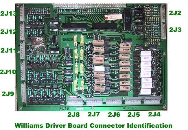
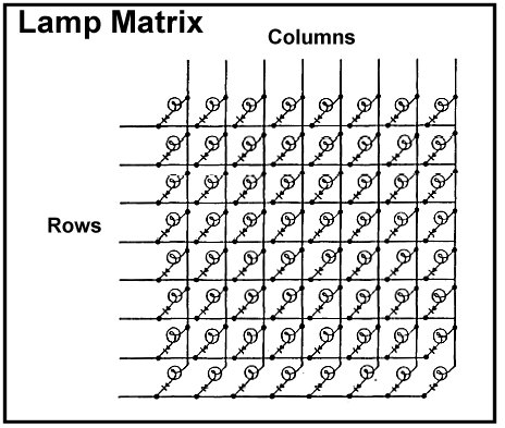
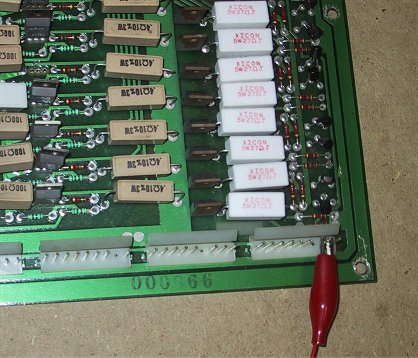
since January 2003: Disclaimer: Standard legal stuff, perform these tests and follow these repair procedures at your own risk. I cannot be held liable for any damage you may inflict on your boards or yourself. 1. Driver Board Architecture The Driver board is an extension of the MPU board. The best analogy to explain how the Driver board is connected would be to think of a personal computer with expansion boards. The slots on the PC motherboard carry all of the computers data, address and ancillary lines onto the expansion board. Other manufacturers of the era used a different architecture, and you could look at their driver boards more like the parallel or RS232 ports on a personal computer. Section 1 of the guide explains some of the reasoning behind this design. 1.1 Driver Board Interconnect The Driver board is mated to the MPU board via what is known as the "40 pin interconnection". There are actually 5 connectors of 8 pins each on each board that make up the interconnection. All of the CPU's address and data lines are carrier over this interconnection, making it the "Achilles Heel" of the design. Dirt and wear can make these connections unreliable and cause your game to lockup, reset or go wild at any point. Every time the Driver board is removed or attached to the MPU board, the solder connections are also flexed, and after time they can develop microscopic cracks that can also cause interruptions on the address and data lines. If you are experiencing intermittent problems with your game, then chances are you have a connector problem. Section 2 of the guide deals with these types of problems and make sure you review it and follow the tips presented there first. 1.1.1 Repairing the Driver Board Interconnect Should you replace all of the connectors in the Interconnection? A good visual inspection of the pins on the Driver board should be done first to make sure none of the contacts have broken. If one or more of the connectors look discolored, this may be the result of a driver transistor "frying" and these connectors should be replaced. You must however, always re-solder the pin connectors or both the MPU and Driver boards. Heat the joints with your soldering iron until the solder melts and flows around the joint. Attempting to diagnose problems without first doing this is a waste of your time. 1.2. Driver Board Functions There are six different circuit types contained on the Driver board: 1. The Solenoid Drives The board also contains 3 PIAs (Peripheral Interface Adapter), Motorola 6821 chips. These interface the various circuits to the CPUs address and data lines. 1.2.1 Solenoid Drives Williams labels the solenoid circuits in its schematics as "solenoid drives", however these circuits actually ground the solenoids. Positive DC is always supplied to the solenoids and they are isolated from ground via the Driver board. This design has proven less complicated (fewer parts = lower cost) and more reliable than "driving" the solenoids with positive DC. Games through System 11 have two types of solenoids, regular (or just "solenoids") and "special" solenoids. Section 1.2.2 describes the difference between the two. Williams games have 16 solenoid lines and 6 special solenoid lines, giving the game the capacity to fire up to 22 coils independently. System 3 through 6 games utilize 5 solenoid lines for sound and speech. Williams added an additional PIA to System 7 boards to control sound and speech, leaving 21 solenoid lines available for game coils (in System 7 games, 1 solenoid line is used for GI lighting effects). Solenoid lines 1 through 16 are triggered solely via the game's program. 1.2.2 Special Solenoid Drives All Williams games in the System 3 through 7 era use a set of what are known as "special solenoids". These are solenoids that can be fired either under game control or directly by a playfield switch. The game's program does not run fast enough to detect and fire the coils for the pop bumpers or the kickers. There would be enough of a lag time from the time the ball runs over a pop bumper skirt switch to the time the game fired the bumper's coil that the game would seem extremely "slow". In order to compensate for this, Williams incorporates six "special" solenoid lines which can be triggered directly from a playfield switch. This circuit bypasses the MPU altogether and fires the coil in real time. For testing and diagnostic purposes, the coil can also be fired by the MPU, and an additional logic IC in the circuit allows the coil to be triggered by both the MPU and playfield switch. You'll notice that there are two sets of switch contacts on a pop bumper and an additional switch connected to the throw arm on slingshot kickers. These are the "scoring" switches, which are activated when the pop bumper for kicker fires. These are required since the trigger switch is not connected to the MPU. There were two exceptions to this rule, Time Warp and Stellar Wars each feature 5 pop bumpers. In Stellar Wars, the lower right pop bumper was driven by the MPU and in Time Warp the designers moved the kickers to the MPU controlled solenoid line. 1.2.3 Lamp Column and Row Drives Your game has the capability of driving up to 64 different lamp positions (with up to 3 bulbs at a position). The lamps are wired in a "matrix" of 8 columns and 8 rows that only requires 16 wires to light 64 different lamp positions. Each lamp is wired to one of 8 "columns" and one of 8 "rows". The MPU then turns "on" a column and a row, lighting the lamp at the intersection. The game actually rotates through the columns one at a time, turning on the required rows for that column. Diodes wired in series with the lamps prevent voltage from "leaking" out and turn on other lamps. 1.2.4 Switch Matrix Like the lamp matrix, the game has a switch matrix of 8 columns and rows that allows up to 64 individual switches to be read. Switches are wired like the lamps in the above diagram, with a switch in place of a lamp. The game will "strobe" (send a voltage) out on a column and then read the rows to see which switches are closed and returning current. 1.3 The Blanking Signal Probably the most misunderstood part of the MPU/Driver board circuitry is the blanking signal. The blanking signal's purpose in life is to turn off or "blank" the lamp, solenoid and display circuits, preventing serious damage to these components in case of a MPU board failure or program lockup. If the signal is low (absent), then the game's lamps, displays and solenoids can't be turned on. In a perfect world, the signal can only be turned on by a running game program on an operational MPU. The blanking signal is set low by a timer circuit. When the game program is running, a signal from the PIA on the MPU board sets the blanking signal high. This PIA signal is sent at a faster rate then the timer is running (resetting the timer), so the blanking will stay high as long as the game is running. If the game program locks up or doesn't start, the timer will expire and set the signal low, turning off the lamps, solenoids and displays. Various posts on the pinball newsgroup, rec.games.pinball, over the years have elevated the status of this circuit to be one of the prime reasons for game failure. Quite the contrary, a missing blanking signal is a symptom of a larger problem (usually a MPU failure). If the blanking circuit is dead, nothing will seem to work. Problems can arise when the connection between the MPU board and the Driver board is bad. Blanking can be checked using you DMM at TP4 on System 6 and 7 boards. On System 3 and 4 boards you'll need to check it at pin 37 of the interconnect. It should read about 5 volts when the board has booted. If you're using the test chip, blanking is also pulsed, so you'll see the voltage vary. Part 4 of the guide contains more information on troubleshooting the blanking signal. There is more information on the blanking in part 4 of the guide. 2. Locked on Coils You don't need any test to tell you that you have a locked on coil. That wonderful smell of burning plastic as the coil melts down is more than enough of an indication that you have a major problem on your hands! You may also hear a "clunk" when you first turn on your machine, followed by the solenoid fuse (F2) blowing. Both are signs of one or more locked on coils, rendering your game unplayable until corrected. 2.1 All Coils lock on when you first turn on the game If all of your coils lock on when you first power on your machine, then your problem usually lies in the inter-board connector. The blanking signal line is probably "floating", looking like its high, along with enough address and and data bus signals to switch "on" the PIA ports, firing your solenoids. Section 1.3 of this document and also part 4 of the guide explain the blanking signal in more detail. Bottom line, if blanking is low (zero volts), nothing will work. However, if there is no connection to the blanking line (blanking is "floating"), the ICs in the driver board circuitry will think that blanking is high. This is why if you have ever powered up your game with the driver board disconnected from the MPU board, but still connected to the rest of the game, all of your solenoids will fire (and hopefully blow the fuse!). Disconnecting and reconnecting the Driver and MPU boards will usually correct this problem on a temporary basis. Check the solder pads on both the driver board and MPU board for cracks, and check the female connector on the driver board to ensure that its still making contact with the pins on the MPU board. 2.2 One coil locks on when first turn on the game If only one coil locks on when you turn on the game, the culprit is probably a shorted transistor on the driver board. To locate which transistor is bad, look up the coil in the game's instruction card. The card will tell you which transistor is used to drive that coil. 3. Testing the Driver board in the game Unlike the non-existent self-tests of the MPU board, the game's diagnostics allow you fully test all of the solenoids, lamps and switches. These tests will let you know that you have a problem, but you will need to do some more digging to isolate the problem as a wiring problem, a coil/lamp problem or a driver board problem. More Information Coming Soon! 4. Testing the Driver board using the Test ROM To test the driver board, you will be connecting it to the MPU board at your bench. Leave the MPU board set up as-is, with the test ROM, power connections and jumpers. (Updated 7/8/03) Connect the driver board to the MPU board at your bench and then reapply power. What you should hear is the relay on the driver board clicking in unison with the LEDs on the MPU board. If the relay does not click, this is an indication that the "blanking" signal from the MPU is either missing or is too short in duration for the relay to energize. This does not necessarily mean you have a problem with your MPU board! I have found that rarely do I get the relay to "click" with System 3 or 4 boards. During normal game operation, the blanking signal is "always" on and not pulsed like it is with the test chip. What it does mean is that if in your game you cannot get the solenoids to energize, the blanking circuit is the first place you should look. In order to perform the majority of the tests described in this document, you need to have the blanking signal high. So if the flipper relay is not "clicking", you will need to override the blanking signal by connecting +5 volts to pin 37 of the MPU board (actually the pin will be sticking out of the connector on the driver board). This is the fourth pin from the left. If you are using a System 6 MPU, you can connect pin 37 to test point 9 on the MPU board for the +5 volts, on System 3 and 4 boards I recommended you connect pin 37 to your power source. Overriding the blanking signal on a
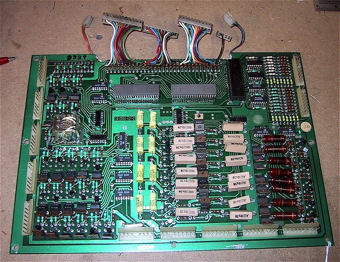
System 6 board: You're now ready to test the PIAs on the driver board with either your Logic Probe or the test LED. To use the test LED, connect the negative end to ground and then touch the positive end to each output on the PIA (pins 2 through 17). I prefer to use a Logic Probe for this since it has a smaller tip. Note, testing the third PIA on the driver board (IC11, the vertical one), you will need to short the pins on connector 2J3 to ground in order to test outputs PA0 to PA7 (pins 2 through 9). Driver Board setup for bench testing lf the PIAs are working, you can move onto the driver tests. I prefer to use the test LED to perform the majority of the remaining tests: Switch Matrix Driver Test - Connector 2J2 Connect the positive side of the Test LED to +5v. Then touch the negative lead to each pin on 2J2. You should see the LED pulse in time with the MPU board LEDs. If you don't get a light pulse on one of the pins, then trace the signal back through either IC17 or IC18. If the PIA has a good signal, but none shows up at the pin, then you need to replace either IC17 or IC18. Switch Matrix Input Test - Connector 2J3 (updated 7/22/03) You need to test the switch inputs at the PIA itself. The inputs are on PIA II (IC11), pins 2 through 9. To test input #1, ground pin 9 of 2J3 and then using your test LED or Logic Probe, look for a pulse at pin 2 of IC10. Then move the ground to pin 8 of 2J3 and check for a pulse at pin 3 on IC10. Continue moving the ground down a pin and checking the next PIA pin (PIA pin 4 to connector pin 7, etc). Lamp Strobe Test - Connector 2J5 This test requires an additional power connection (see below). Connect +5v to any pin on connector 2J4. Remove the positive connection of the Test LED from the +5v connection. Then connect the negative side of the Test LED connected to ground. Perform the test by touch the POSITIVE side of the Test LED to each pin on connector 2J5. If you don't get a flash, check the input to the IC controlling the pin (IC13 or IC14). If you have an input then you'll need to replace either the TIP42 or the pre-driver 2N6472. The test LED won't show the output of the IC due to the short signal pulse.
Lamp Row Test - Connector 2J7 This test also requires a +5v connection to any pin on connector 2J4. Additionally, it requires a ground connection to any pin on connector 2J6. Connect the positive lead of your test LED to the +5v and then using the negative lead, you can touch each pin on connector 2J7. If you don't get a flash, you can use the test LED to trace back all of the components to the PIA.
Solenoid Line Test - Connectors 2J9 and 2J11 No additional power connections are required for this test. Connect the positive side of the test LED to the +5v and then using the negative lead of the test LED touch it to each pin on connectors 2J9 and 2J11. If you don't get a flash, or get a steady light, trace back through the driver (TIP120) and the pre-driver (2N4401) for a signal and finally back to the corresponding 7408. Special Solenoids - Connector 2J12 The special solenoids are not controlled via the MPU during normal game play, so we need to do a slightly modified test for each line. First, connect any pin on connector 2J10 to ground. Connect the positive side of your test LED to +5v. Now you can test the first special solenoid output on pin 3 of connecter 2J12. Connect pin 2 on connector 2J13 to ground. Then touch the negative side of the test LED to pin 3 on connector 2J12. The light will pulse in rhythm with the LED flash on the MPU board. You repeat these tests for the
remaining lines by moving the ground connection on 2J13. To test: To trace the signal if you don't get a flash, leave the test LED connected and move the ground from its pin on 2J13 back through the components. Use the test LED described at the beginning of this document for this test, using a Logic Probe will not always give you a true reading as to the condition of the circuit. (Update 1/8/03) - You will get different results from this test depending on the duration of blanking signal from your MPU board. If you have overridden the blanking signal by applying +5 volts directly to pin 37 of the interconnect, your results will appear as documented above. If the blanking signal from the MPU board is long enough in duration that the flipper relay "clicks", the test LED may pulse on all special solenoid pins without grounding the corresponding pin on 2J13. If this is the case, when you do ground the pin, the LED will remain lit (or the brightness will vary with the pulse). This is a "good" result and means that driver is operating properly.
|
|
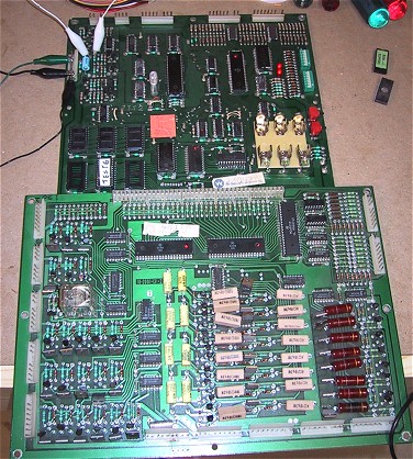
How not to repair a board! If you ever wanted to know what the term "hacked board" means then read on. I received the driver board pictured below in for repair a while back The entire interboard connector has been "nibbled" out (a job in itself) and replaced with plug connectors. The even more interesting part is that all 3 PIAs have been replaced, however the originals were cut off, the legs left in the board, and new ones soldered to the existing legs! The same was done with all 4 ICs in the switch matrix. Needless to say, I declined the repair job.
|

 For
this test, apply +5v to any pin on connector 2J4.
For
this test, apply +5v to any pin on connector 2J4.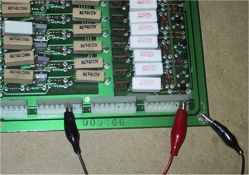 This test requires a +5v connection to any pin on connector 2J4 as will
as a ground connection to any pin on 2J6.
This test requires a +5v connection to any pin on connector 2J4 as will
as a ground connection to any pin on 2J6.