Step 5: Mount drop target banks.
As noted above, the playfield is a bit cramped. This is further complicated by the fact that the two target banks are angled toward each other. I had to do some cutting of the target bank assemblies to get them to fit. A Dremel tool with a cutting wheel works well for this.
As I recall, I had to cut off one or more of the mounting feet on one or more of the drop target assemblies.
Again, neatness counts. Be sure to center the targets themselves within the oval cutouts and align them nicely. A sloppy job will only bring you the ridicule of your friends as you show off your work.
Step 6: Wire drop target reset coils.
The backbox wire harness brings the solenoid wires up to the connector that mates with the playfield harness. To do a really neat job, find some Molex-type pins to insert into the playfield harness connector to bring the signals down to the playfield. If you connect directly into the backbox harness, you will not be able to remove the backbox when you have to move your Firepower through a narrow doorway.
(I was able to work the pins out of the connector on the above-mention Disco Fever harness, and use the whole wire for the conversion.)
Solenoid #2 is the left bank reset (1-3 targets) (Grey-Red wire)
Solenoid #3 is the right bank reset (4-6 targets) (Grey-Orange wire)
Wire the drives to the lug of the coils that are connected to the anode of the diodes (side WITHOUT the stripe). Refer to another coil on the playfield to double check.
Connect power to the coils. Use a Red wire and tack on to a nearby coil. The power goes to the coil lug connected to the cathode of the diode (side WITH the stripe).
Step 7: Wire the switches.
The drop target switches are wired in the same place in the matrix as the standups. That information is as follows, from left to right:
"1" drop target - switch 17 (Green-Orange/White-Brown)
"2" drop target - switch 18 (Green-Orange/White-Red)
"3" drop target - switch 19 (Green-Orange/White-Orange)
"4" drop target - switch 22 (Green-Orange/White-Green)
"5" drop target - switch 22 (Green-Orange/White-Blue)
"6" drop target - switch 23 (Green-Orange/White-Violet)
The early style drop targets (horseshoe/wiper) had two sets of contacts -- momentary and continuous. The momentary are activated while the drop target is on its way down, and the continuous are activated while the the target is resting in the "down" position.
The easy way to connect the drop targets is to simply use the continuous contacts on each target and connect it as listed above. This is the way later style (Black Knight and later) drop targets would be wired.
The original Firepower, however, used the momentary contacts connected as above. The continuous contacts were connected in series within each bank, and connected into another place in the matrix. This gave the software an extra piece of information that all the drops in a bank were down. You can connect your drop switches this way, but its extra work that is not necessary. Here are the switch positions:
"1-3" drop target series - switch 20 (Green-Orange/White-Yellow)
"4-6" drop target series - switch 24 (Green-Orange/White-Grey)
The "10-point" switches are wired as follows:
"1-3" drop target standup - switch 55 (Green-Violet/White-Violet)
"4-6" drop target standup - switch 52 (Green-Violet/White-Yellow)
When wiring switches, note that the White wire is connected to the anode of the diode (side WITHOUT the stripe), and the Green wire is connected to the switch terminal NOT connected to the diode. Refer to another switch on your playfield as a guide.
Step 8: Double check your work.
Especially make sure that your coils are wired correctly. If you reverse the leads on a coil, you will blow up the solenoid driver transistor. The Red (power) wire goes to the coil lug connected to the cathode of the diode (side WITH the stripe).
Check the wiring of the switches. If switches are incorrectly wired, they can mess up other switches in the matrix.
Step 9: Test your work.
Run test mode on your game and check out the solenoids and switches to verify the correct installation.
Step 10: Play your game.
Notice that the default "light kickback" rule now makes more sense: The kickback is lit on "1-3" or "4-6" on the same ball or spotting the "1-6" lamps. Now that you have drop targets, you can actually keep track of the "1-3" or "4-6" on one ball.
 Misc:
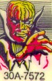
The drop target stickers used on Firepower depicted the "melting man" as shown elsewhere on the game. They sport the
part number 30A-7572. These were available
from Action Pinball (www.actionpinball.com)
as of August of 2001. This is a scan
of an actual target sticker that I bought from Ray.
Misc:
The drop target stickers used on Firepower depicted the "melting man" as shown elsewhere on the game. They sport the
part number 30A-7572. These were available
from Action Pinball (www.actionpinball.com)
as of August of 2001. This is a scan
of an actual target sticker that I bought from Ray.