 |
|
 Did you know
that Firepower was originally designed to use two banks of 3 target Drop
targets instead of stand-up targets? Did you know
that Firepower was originally designed to use two banks of 3 target Drop
targets instead of stand-up targets?
Prototype versions of the game were produced this way, with early games still containing the wiring and cutouts for the targets. The popular thought is that the drop targets were replaced with stand-ups to reduce the final cost of the machine. Another thought is that the drop targets would be too much of a maintenance problem so close to the flippers. |
|
 |
|
| This page documents my Firepower Drop Target Retro-fit project with photos and step-by-step instructions. If you're thinking about taking on the project on yourself, it will give you a good idea of what is involved. The original instructions for completing the project were first documented by former Williams programmer Ted Estes on the rec.games.pinball newsgroup in 1995. You can read Ted's original text here. I followed Ted's text almost verbatim, but needed to alter a few steps. I would highly suggest reading and printing Ted's instructions as part of your project. (Update on 3/10/02 - Ted and I have exchanged several emails after this page was initially posted and I've updated the page to incorporate his feedback. Thanks Ted!) | |
|
|
| The
Great Drop Target Mystery: Firepower was one of Williams most popular and successful games ever. Over 17,000 games were produced, ranking it second in units produced bearing the Williams name (Flash holds the record at over 19,000 units and The Addams Family at 21,000 units, Williams most popular game, was released under the Bally label). Most all Williams games of the early SS era (late 70s and early 80s) featured drop targets. Games like Flash and Time Warp sported 8 targets each. So why did Firepower wind up with 9 stand-ups instead? The original design of the game called for drop targets in place of the stand-ups in the middle of the playfield and the prototype and sample games were actually produced this way. |
|
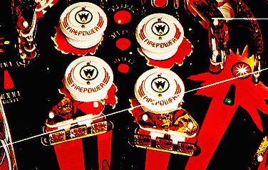 (Williams Firepower Flyer) |
If
you look closely at the Firepower advertising flyer put out by Williams,
you'll notice that it shows the game with the drop targets installed.
What is also interesting about this flyer is that there is no mention made about the targets or their scoring abilities. Just about every other feature of the game is highlighted!
|
| The game used for the flyer shoot is
one of the testing prototypes and is the case of some games will show
marked differences from the production game. Flash had different
target colors and decals in its flyer. |
|
| When
the game was released, it featured stand-up targets instead of the drop
targets. There are two popular myths about why this change
was made. The first is that the game cost too much to produce and
replacing the drop targets with the stand-ups was the easiest way to cut
the cost without eliminating any game features. The second is that
the targets, being in direct line with the flippers, took too much of a
beating and would be a maintenance nightmare. I tend to think that
both are correct, that prototype games showed problems in high volume
locations during multi-ball play and when it came time to make a
decision on what to remove to keep manufacturing costs down, the drop
targets got the axe with no complaints.
The programming code didn't require any alterations, nor were any playfield modifications required. This made the change-over seamless for Williams. The first playfields manufactured still had the cut-out for the scoring switches that were originally used behind the targets, but later runs eliminated this cutout. The wiring harness was modified in later runs to eliminate the two extra wires required for the target reset solenoids also. The game plays almost virtually the same. Hitting all three targets in one bank lights the right out lane kickback. Hitting all six targets the first time lights two of the three ball locks, hitting all six a second time locks the third ball lock in preparation for multi-ball. So if you see a game today with Drop Targets, it is either a prototype game or was converted by its owner or a previous owner to use Drop Targets. |
|
|
|
| Converting
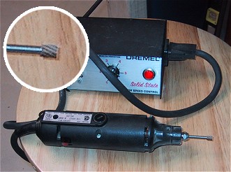
Your Game, Step 1 - What's involved: Lets face it, Drop Targets are more fun than stand-up targets, and you've convinced yourself that you want to convert your game. This was my thought over 2 years ago when I first read Ted Estes' conversion instructions. Just getting started in the hobby, they seemed a bit daunting, especially that part about routing out the playfield! I made a copy and put the project on the back burner for a year and a half. With having successfully restored a few games under my belt, I decided to give it a try. The first thing I did was to obtain another Firepower game. I wasn't about to ruin my favorite game if the project turned out to be a bust. I have actually acquired three additional Firepowers in the last 2 years with the intention of restoring and selling them. I picked the best of the three playfields to do the conversion on. The conversion took me about a week of evenings, working about 3 hours a night, to complete. If you had a full day to dedicate to the project, you probably could get it done in a single session. Unless you have a very early playfield, you will need to cut your playfield to fit the "10-point" switches behind the drop targets. I would suggest not attempting this with a hand-saw or a power drill. I used a Dremel tool, which is about the only thing I can think of that can work in the tight confines of a populated playfield. A Rotary "ZIP" tool may also work. You will also need to drill pilot holes for mounting the drop target assemblies. This requires nothing more than a small power drill. Other than the cutting, most of the work involves wiring and soldering in the Drop Target switches. I would also recommend disassembling and cleaning your drop target assemblies. No work is required in the backbox, and there are no electronic modifications required since the software still has all of the code required to drive the drop targets. |
|
|
|
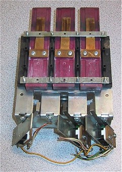
| Step
2 - Parts and Tools Required: You will need to obtain the following parts: - Two three-bank drop
target assemblies. These need to be from a Williams
System 3, 4 or 6 game. These are the type that have "horse
shoe" wipers. See below for more info on drop targets and how
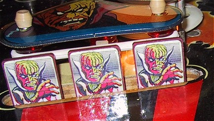
to get them. - Two .093" Molex Male Round Crimp Connectors - If your playfield doesn't have the switch cutouts, then your wiring harness won't have the two drop target reset solenoid lines either. You'll need to add these two wires to the playfield harness and connector. Don't even think about bypassing the connector and hard-wiring these two lines in. If you're using an older playfield to obtain parts, you could remove the pins from an existing connector, but you'll need an extraction tool to do this. Pulling the wires out of a connector will bend the locking prongs back and render the connector useless. You should have these and the extraction tool in your toolkit anyway. - Wire Ties - You'll need a good handful of small 3" wire ties to keep your work neat. - Drop Target Decals - Get a set of Firepower Drop target decals from either Ray Johnson (http://www.actionpinball.com) or Alan Myer (Pinball Express, see his ads in Gameroom Magazine). I would highly recommend getting a playfield from a Williams game of the same era that you can use for parts. It will have the stand-up switch assemblies you need, may have the drop targets and will have the color coded wire you'll need to do the project properly. Tools required: - Dremel Moto-Tool. You'll need this for making the cutouts for the switches. I used a high-speed cutting bit in mine to route out the cutout. Better yet would be to have the routing attachment and a routing bit. You'll also need a cut-off wheel if the drop target assemblies you get have mounting wings on them.
|
|
|
|
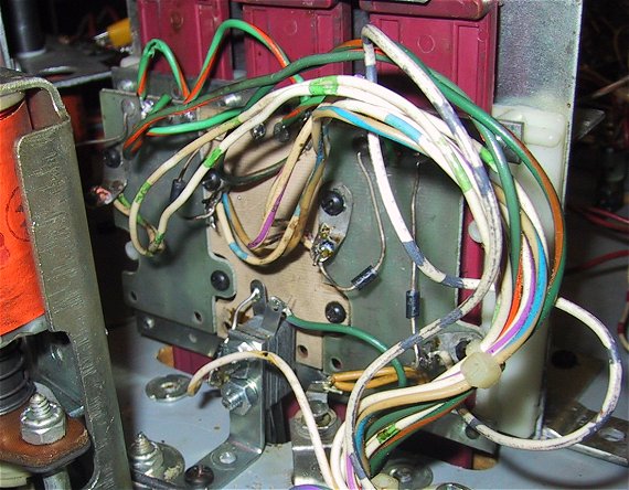
| More
about Drop Targets:
Williams Drop Target assemblies have evolved over the years. Drop target assemblies used in the early Williams Solid State games used what is commonly known as a "horse shoe" wiper. |
|
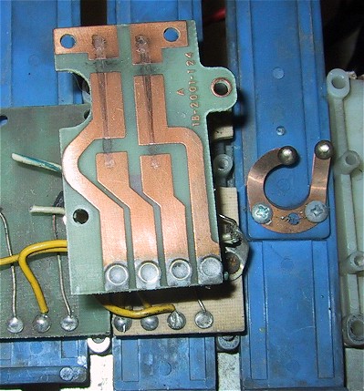 |
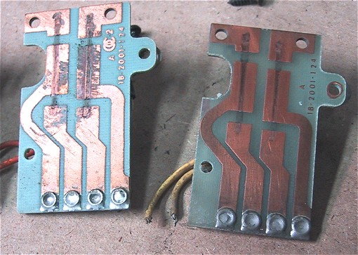
This photo shows the back of the contact plate and the drop target wiper
from a target assembly off of a Flash. All System 3 through 6
games used this type of assembly that had two sets of contacts for each
target. The first contact was a "momentary" contact that
was engaged when the target was in the process of dropping and the
second contact was a "continuous" contact that was closed when
the target was fully down.
The target assembly was wired so that each momentary contact was wired directly into the switch matrix and the continuous contacts were wired in series as one switch that would be closed when all of the targets were down. Drop Target assemblies off of later Williams games (System 7 and System 9 games) use a single switch at the bottom of the target to trigger a target down event. |
| So
why all of the extra wiring and funky horse shoe wiper? Why did it
take until System 7 games for Williams to move to using a single switch
per target? This design was used during EM days with the continuous
contacts used to trigger the target reset and one would have thought
could have been retired with the advent of the Solid State machine. The answer to this
seems to lie in the capabilities of the
early MPU and Driver boards. These boards can only reliably register two
switch closures at the same time on the same row/column. Having the
drop target switches closed all the time would render the game
inoperable. Using this arrangement meant that only one switch, maybe two
if two targets go down at the same time, would be closed at one
time. If you look closely at the switch matrix on these early
games, you will notice that switches that are likely to remain closed
during game play are all on different row/columns. For Firepower,
the ball trough switches and eject hole switches are all wired on
different row/columns.
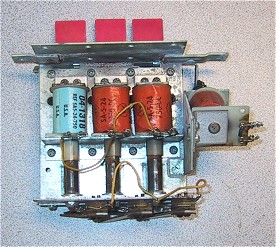
System 7 MPU boards (Black Knight and later) were modified, along with the driver board, to allow more than 2 closures to register properly. Attempting to use a pre-System 7 driver board in a System 7 game causes the game stop reading switch closures after two switches are down on a row/column. Below are shots of the front and back of a System 7 drop target assembly. System 7 games used drop targets to their fullest capabilities. The target assembly below could reset individual targets and pull down all of the targets. Notice the leaf switches at the bottom of each target.
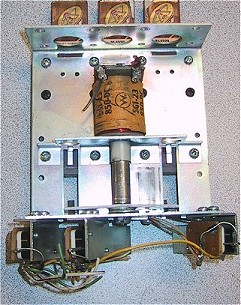
System 9 games switch from leaf switches to micro-switches to register target drops (drop target assembly from a Space Shuttle):
|
|
|
|
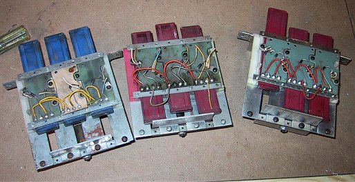
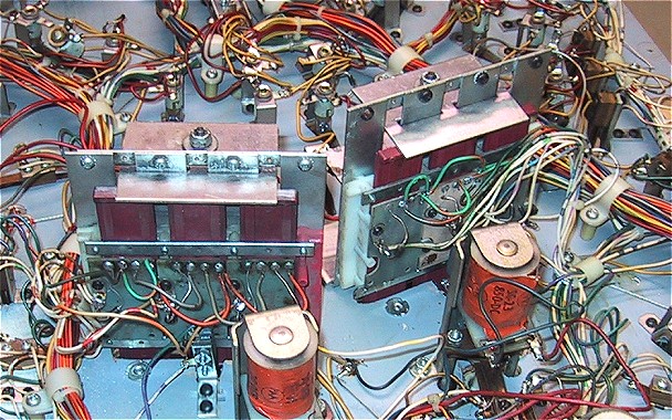
| Step
3 - Get the right drop target assemblies!
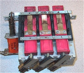
For my Firepower retrofit project, I put a "part wanted" ad on the Mr. Pinball mailing list/web site looking for early Williams Drop Target assemblies. This was before I knew about that you couldn't use newer (system 7 or 9) targets on a system 6 game. Reading Ted's article, you may be lead to believe that you can, but the fact is that only older target assemblies will work for this project. I received a good deal of emails with offers for target assemblies, with prices all over the place. One seller who had two Gorgar assemblies (perfect!) even sent me two Alvin G. & Co. assemblies in addition to the Gorgar assemblies because of the poor shape of the Gorgar targets (the targets were unusable and are in my junk drawer now). Another person sent me a target assembly free and just asked for postage back! You will probably buy a few assemblies that aren't what you thought they are, most sellers have no idea what the difference is won't even bother to look and tell you if there is a PC board on the back. You should expect to spend between $10 and $20 for decent shape old style assemblies. You also will probably need to buy more than two to get two decent working assemblies. Below are the three target assemblies I started with to get my final two. The assembly on the left had decent contacts, but was the wrong color, so I rebuilt the one of the right using the contacts from the one on the left (from a Flash). You should also notice that the center target does not have any "wings" or mounting tabs. If yours have these tabs, one side will need to be cut off to get the assembly to fit.
This is the reason you buy more than two drop target assemblies. The contact plate on the left came from what looked like the best of the bunch externally, but turned out to be worthless. The contact plate on the right is almost brand new in comparison. I rebuilt the good looking assembly with the good contacts.
|
|
|
|
| Step
4 - On to the Playfield... Remove the old stand-up Targets Remove
the playfield from the game and set it up at your bench upside
down. The first thing you need to do is to remove the 6 existing
round stand-up targets. You can unsolder the leads, or take the
easy way out as I did and cut them at the switch. Save these
target assemblies, they're worth a few bucks each. Keep the screws
handy, you'll use them to mount the drop target assemblies. |
|
|
|
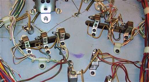
| Step
5 - Move the GI wiring out of the way
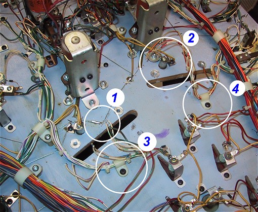
In the photo below, you'll notice that areas 1 and 2 are directly centered behind the target opening where our new standup switches will go. Area 1 is the GI bus and area 2 is the GI light behind the 1-2-3 target area. I rerouted the GI bus by cutting out the bus wire and replacing it with insulated wire. For the GI light is area 2, you can flip the mounting bracket around. It will overlap the t-nut for the playfield post, so just put some electrical tape over the t-nut before screwing down the lamp. I've circled areas 3 and 4 to point out the wire clips. They use a set of screw holes were evidently originally meant for the drop targets. These holes will allow you to align your targets almost perfectly.
|
|
|
|
| Step
6 - Cut out the playfield for the stand-up switches. This is the most critical step in the process. Mess this up and you will have a ruined playfield (or at least an ugly one!). You need the right tools to do the job. Although you can cut the hole with a small saw or a drill with a large bit, I wouldn't recommend those methods. Use a Dremel tool with a cutting or routing bit or a Rotary ZIP tool with a cutting bit. If you have a routing attachment for your Dremel tool, you should make the cut from the top of the playfield. The routing guide will not fit on the underside. I don't have one, so I opted to cut "free-hand" with the Dremel from underneath the playfield. Don't attempt to cut free-hand from the top, as the moto-tool has a tendency to "jump" and could gouge the playfield surface. Mine did jump on me a few times, but since I was cutting from the bottom, no damage was done. Measure and mark where you want to cut. I first found the center of the existing cutout, then drew a line back 7/8". The cutout width should be 1/2" (I measured another machine), and I drew in a "U" centered on my first line.
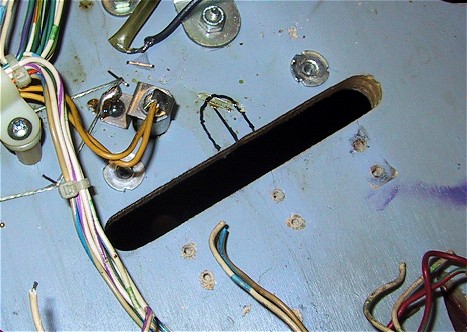
Make your cuts! You'll want to taper the cut where it meets the current cutout. I did this with a finishing wheel and not the high speed cutter. My photos of the cuts from the underside were deleted somehow, but below is a shot from the top (don't do your cutting with the rubbers or post in!)
Here is a mistake I made:
Leave your switches on the bench until after the target assemblies are mounted. |
|
|
|
| Step
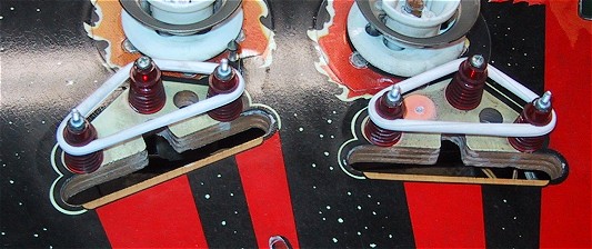
7 - Mount the Drop Target Assemblies. The first thing you'll want to do is to test fit the target assemblies. I actually did the test fitting before I made the cutouts, but it can also be done afterward. You'll notice in the photo that one of the target assemblies has a mounting "wing" that will need to be cut off. The other wing can stay.
After cutting off the wing on the one target (this was all the trimming that was necessary), I mounted the targets using the screw holes that the wire clips were in (see step 5 above). I tightened these down as much as I dared and then flipped over the playfield to make sure the assemblies where centered in the opening. After adjusting them so they were, I carefully flipped the playfield back over and marked all of the screw locations on the playfield with a permanent marker. To insure I didn't lose my centering, I drilled a pilot hole while the assemblies were still mounted and threaded in a second screw on each assembly. I then removed the assemblies and drilled the remaining pilot holes for mounting the assemblies. I did not however reattach and mount the target assemblies at this point. If you do, you will have to do the soldering of the switches with the targets mounted. It seemed to me it would be quite a bit easier just to lay the assemblies down on their backs and work on them while they were level.
|
|
|
|
| Step
8 - Getting ready to wire the Drop Target Assemblies. This step took a lot longer than I had planned. Not all of the wires you need are in your existing wiring harness. You'll need to add 7 new wires into the harness and tack the solenoids into the their power. Important Note - Ted's original documentation states that you can use either only the "continuous" contacts or the "momentary and continuous" contacts on the drop targets. From my research on the web gathering experiences from people who have attempted this in the past and knowing about the limitations of the switch matrix, I feel that this may not be the case. System 3 through 6 MPU/Driver board combinations could only reliably read two switch closures on the same row or column. All of the drop targets in Firepower are wired onto the same column in the switch matrix. At a minimum, you would need to remove resistors R204 through R210 on the driver board and replace them with jumpers or use a System 7 Driver board. I don't know if this limitation would be corrected by just the Driver board modification or if the System 6 CPU board itself was also part of the limitation. To be on the safe side, I highly suggest wiring the drop targets with both sets of contacts. You'll need to obtain about 5' or 6' of the following color coded wire for the new switch connections that don't exist in the game. This is where that old playfield comes in handy! I would highly suggest getting color coded wire from an old playfield. It will be extremely difficult to troubleshoot wiring problems if you use new solid wire.
Gray-Red Drop Target Switches: "1" drop target -
switch 17 (Green-Orange/White-Brown) Drop Target "continuous" Switches: "1-3" drop targets -
switch 20 (Green-Orange/White-Yellow) "10-point" Switches: Solenoid power: Solenoid #2 reset (1-3 targets)
(Gray-Red wire) |
|
|
|
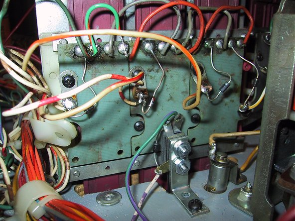
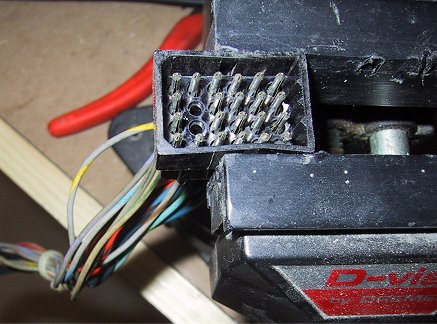
| Step
9 - Wiring the Drop Target Reset Solenoids The two reset solenoids need to be connected into the wiring harness. The head portion of the harness already has the proper wiring and connections, however the playfield harness is missing the wires. If you look at the Molex connector, you'll see the two missing connections that need to be added.
Thread a gray-red and a gray-orange wire from the Molex connector to the drop targets. The gray-red goes to 1-3 target and the gray-orange goes to the 4-6 target. I used additional wire ties to attach these wires to the harness, leaving the existing ties on. Unless you have a wire tie tension tool, its best to keep the current ties on as you won't be able to tighten the ties enough to keep things neat. Crimp on a Molex connector to the end of each wire and insert the gray-red wire into hole #18 (next to the gray-brown wire) and insert the gray-orange wire into hole #19 (next to the gray-yellow wire). Back at the Solenoids, solder the wires to the lug of the coil that has the un-banded (anode) side of the diode. The other lugs of the solenoids need to get connected to the red (power) side of another solenoid. I used 18 gauge red wire and daisy chained the two drop target solenoids together and then connected them to the eject hole solenoid. |
|
|
|
| Step
10 - Wiring the "new" switch wires There are four new switch wires that need to be run to connect the continuous (all targets down) switch of the drop target banks into the switch matrix. Looking at the target assembly from the rear you need to connect the Green-Orange wire to the solder pad second from the left (see photos below). The white-yellow and white-gray wires connect to the solder lug on the far right of the target (un-banded side of the diode). "1-3"
drop target series - switch 20 (Green-Orange/White-Yellow) For the "10-point"
switches you'll need to wire them as follows: The Green-Violet wire goes to the lug without a diode connection on both switches, the white-violet and white-yellow wires go to the lug that the un-banded end of the diode is connected to. |
|
|
|
|
|
| Step
11 - Wiring the drop target switches This is the home stretch! You just need to wire the 6 target switches and and you're ready for testing. These get soldered to the lugs on each target (and to the non-banded diode). Some switches will have two wires, some only one, depending on how the targets were originally wired and daisy-chained: "1" drop target -
White-Brown The Green-Orange connection has already been made when you wired up the continuous switch connection. |
|
|
|
| Step
12 - Secure the Target Assemblies and Switches The last step in the project is to secure the drop target assemblies and switches to the playfield. I recommend waiting until after you have wired everything to put them in place. As you can see from the photo below, things are much tighter with the drop target assemblies in place. If you haven't yet, drill pilot holes carefully, the last thing you need to do is to go through the playfield. Use the screws that you saved from the stand-up targets to secure the target assemblies and switches. Wait until you test the playfield in your game before securing all of the wires with wire ties.
|
|
|
|
| Step
13 - Testing and Trouble-Shooting Reinstall the playfield in the game and reconnect the wiring harness. When you start a game the two target reset solenoids should fire. If they don't, stop at this point and go over your wiring. If the targets reset properly, manually drop each target and check to see that the bonus increases and the corresponding target light stays on. If you've wired the targets incorrectly, you'll see different lights come stay on when a target is dropped. The targets should reset when all three targets are down. If they don't, then check the continuous circuit wiring. Also test the two 10-point switches. For whatever reason, they give 50 points on my game, but they're referred to in Ted Estes' original documentation as 10-point switches. You'll need to adjust these switches pretty severely in order for them to register properly. |
|
|
|
| Step
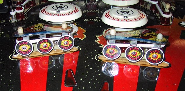
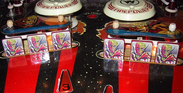
14 - Enjoy your game! (and closing comments) Now its time to play you "retro" Firepower. You'll notice quickly that the game plays quit differently. The 6 targets the focal point of the game and about 50% of your shots usually hit the target area. My Pros and Cons: I love drop targets in older games, they give another good piece of visual and audio (the "thunk" when they reset!) feedback. The drop targets in Firepower add to the visual aspect of the game and drastically alter the scoring (see the "Great Drop Target Mystery" at the top of the page). They do however slow the game down. Hitting the standup targets dead on would accelerate the ball back to you at an amazing speed. The drop targets seem to absorb a good deal of the ball's momentum. With the stand-up targets, you could "brush" them with the ball on its way up the playfield, not so with the drop targets, they require a more solid "hit" to knock them down. After playing both versions of the game, I still prefer the production stand-up target version. I plan to but both games side by side in the game room and it will be interesting to hear what feedback I get from other players. I took the game to the Allentown Pinball Wizards Convention in May of 2002 and received a lot of interesting feedback on the game. Most people agreed with my assessment of the drop-target version, a ton of fun to play, but the original still has more speed. The scoring is definitely harder than the stand-up target version, with over 250 plays the top score was only 145,000! Before: After:
|
|
 \
\
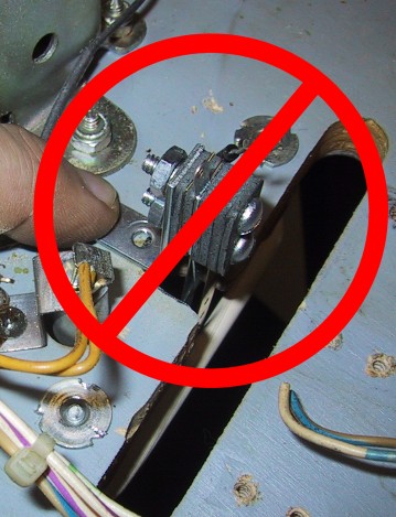 With
this photo, I was intending to show you how to figure out where to
mount the 10-point switch. I was tempted to center it in the
cutout so the blade was making contact with the rubber on the top.
Wrong! The switch needs to be mounted at the rear of the cutout to
clear the target assembly when its mounted.
With
this photo, I was intending to show you how to figure out where to
mount the 10-point switch. I was tempted to center it in the
cutout so the blade was making contact with the rubber on the top.
Wrong! The switch needs to be mounted at the rear of the cutout to
clear the target assembly when its mounted.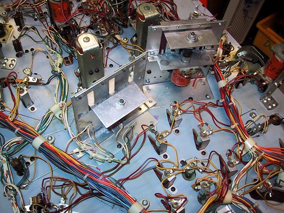

|
Back to Mark's Pinball Page!
It is currently 12:13:04 AM (Eastern) on Tuesday, October 22, 2024 |